Terrain>Surfaces>Current Plane
The Current Plane functionality allows the creation of a planar inner surface.
The plane is created by specifying the various parameters that the system uses to generate the plane. The definitions of these parameters are shown in the following figure:
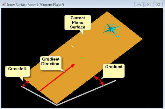
The Current Plane is defined by a direction, gradient, cross-fall and height reference. Note that the crossfall is typically 0.0 (no cross fall), the gradient can also be set to 0.0 creating a horizontal surface.
When the Current Plane command is selected the Current Plane, dialog is produced. The first page of the Current Plane dialog is the Slopes page:
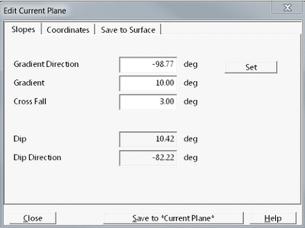
The Slopes page contains the following elements:
Gradient Direction field. This field contains the direction, relative to North, of the gradient. The gradient direction can be keyed in if it is known, alternatively it can be set graphically using the Set button.
Set (set gradient direction) button. When clicked this button temporarily dismisses the Current Plane dialog. Focus moves to the Terrain Window where the Terrain Cursor responds to mouse movement. the Terrain Cursor is moved to a start point and a left click is performed. As the Terrain Cursor is moved further a direction arrow is dragged out indicating the Gradient Direction. When the arrow is pointing in the appropriate direction a second left click registers this direction which is placed in the Gradient Direction field.
Cross Fall. If a cross fall is required to cross fall angle is placed in the cross-fall field.
When the Gradient and Gradient direction are defined the user clicks the Coordinates tab to open the Coordinates page:
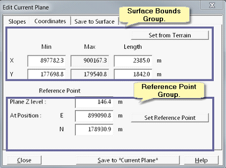
At the top of the coordinates page is the Surface Bounds group. The fields in the Surface Bounds group allow the user to key in the coordinates for a minimum and maximum point which will define a bounding rectangle for the Current Plane surface. This determines the planar extents of the surface. There is also a Set from Terrain button. If the Set from Terrain button is clicked the bounds of the Current Plane surface are set to the bounds of the Terrain Surface. If the user takes no action in the Surface Bounce Group, the Current Plane is automatically set to the bounds of the Terrain Surface. As this is typically what is required, there is usually no need to modify the Surface Bounds.
At the bottom of the Coordinates page is the Reference Point group. Having previously defined the Gradient and Gradient direction, the elevation of the Current Plane must be defined. This is done via a reference point. The Reference Point is a point on the plane where the elevation is known. This is typically set using the Set Reference Point button. When the Set Reference Point button is clicked a Current Plane, dialog is temporarily dismissed and focus returns to the Terrain Window. The Terrain Cursor is active in the Terrain Window and its move to a location on the terrain will the elevation of the Current Plane is known. This is usually a point where the Current Plane it intersects the Terrain Surface. When the Terrain Cursor is at this reference point left click is performed. This Set Reference Point dialog is produced:
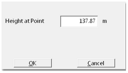
The Set Reference Point dialog has a field in which the reference point height is entered. By default, this is the elevation of the terrain at the nominated reference point. As the Reference Point is typically the point where the Current Plane intersects the Terrain Surface, this default value is often the required value of the Reference Point. When the Reference Point number has been entered the OK button is clicked and focus returns to the Current Plane dialog.
At this stage the Current Plane is fully defined as ready to be saved. Clicking on the Save to Surface tab opens up the Save to Surface page:
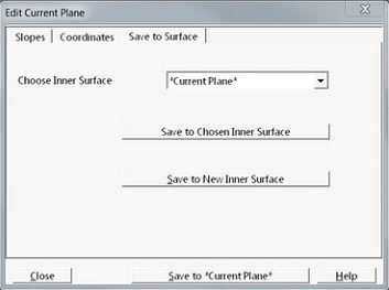
There are three options for saving the plane.
Using the Choose In a Surface pulldown list an existing In a Surface can be selected. When the Saved to Chosen In a Surface button is clicked the surface defined by the Current Plane set up will be saved in to the nominated In a Surface.
Clicking the Saved to New Inner Surface button produces a dialog which allows the user to name a new In a Surface. The surface defined by the Current Plane set up will be saved to this surface.
At the bottom of the dialog is a button named Save to *Current Plane*. When this button is clicked 3d-DigPlus creates a special surface named *Current Plane*. The surface defined by the Current Plane set up will be saved to this surface. If the Current Plane command has been run previously and the *Current Plane* surface exists, clicking the Save to *Current Plane* button will overwrite the existing *Current Plane* surface with the new Current Plane surface.