In 3D-Dig
Terrain>Surfaces>Construct Inner Surfaces
Must be in cross section view
The construct surface command allows an inner surface to be constructed via a cross section window. The user draws the profile of the inner surface in the cross-section window, the Construct Inner Surface command then creates a three-dimensional line based on this profile and the cross-section location, this is known as the seed feature line. The system creates a new inner surface and the newly created seed feature line is placed in the surface. Two additional copies of the seed feature are created on either side of the original feature. The offset distance between the original seed feature and the copies is controlled by user settable parameter. When the process is complete the system triangulate and grid is the new inner surface.
Before initiating this command, a suitable cross-section must exist and its section window must be active. The cross-section at approximately the centre of the required surface and normal to the axis of the surface. When the command is initiated the Construct Inner Surface dialog is produced:
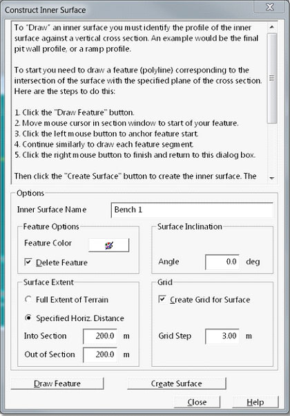
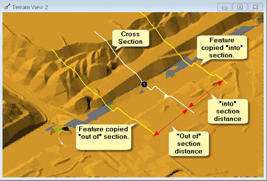
The name for the new surface is entered in the Inner Surface Name field. The Surface Extent group contains settings which control how far the new surface will extend relative to the section line. If the option Full Extent of Terrain is selected the surface will extend, normal to the original section line, to the full extent of the Terrain Surface. If the Specified Horizontal Distance option is selected the surface will extend beyond the original cross-section by distances specified in the to field is Into Section and Out of Section. This is illustrated in the figure below. Note that in this figure two features copied to form the surface are shown on the Terrain Surface, these features only exist in the data for the newly constructed surface:
To command can optionally generate a grid model of the surface and this function is controlled by the Grid group. Selecting the checkbox Create Grid for Surface and specifying the Grid Step will result in a grid model being produced.
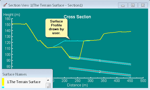
To design the surface the user clicks the Draw Feature button. The Construct Inner Surface dialog is temporarily dismissed and focus moves to the Cross Section window. The user draws that design surface profile in the Section Window by pointing and left clicking. When the feature is complete a right click terminates this process and returns focus to the Construct Inner Surface dialog. The figure below shows a surface profile for a bench surface drawn in the section window:
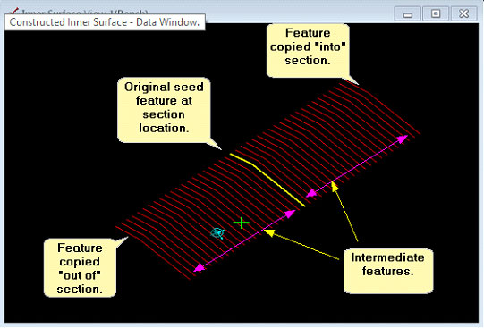
To complete the process to Create Surface button is pressed. This results in the system constructing the new Inner Surface according to the user specifications. The figure below shows the surface constructed as described above in a data window: